
Engineering Drawing Project Assignment
Author: Junhan Chen
Course: MEC106 Engineering Drawing
Institution: Xi’an Jiaotong-Liverpool University
Date: Nov 2024 – Dec 2024
Software: Creo Parametric
Project Overview
This coursework project focuses on engineering drawing and CAD modelling, with an emphasis on orthographic projection, multiview representation, and isometric sketching.
Orthographic drawings allow three-dimensional objects to be represented through multiple projection views (typically front, top, and right-side views). When objects are positioned correctly relative to the projection planes, their geometric features can be represented in true scale in one or more views, making multiview drawings one of the most accurate methods for describing engineering components used in manufacturing and construction.
The project also develops the ability to create isometric sketches, a form of parallel projection that represents three dimensions in a single drawing while preserving consistent scale along the principal axes. These sketches provide a clear visual representation of spatial geometry and complement traditional multiview drawings.
Outcomes
Through completing this coursework project, the following competencies were developed:
- understanding of engineering drawing standards and conventions
- application of orthographic projection to analyse engineering solids
- construction of isometric representations from multiview drawings
- development of spatial visualisation and geometric reasoning
- practical use of Computer-Aided Design (CAD) tools
- preparation of a structured engineering-style technical report
Section A – Isometric Sketch and Multiview Drawings
Assignment Requirement
Three components were provided in orthographic view.
The task was to produce complete engineering drawings by hand, including:
- multiview drawings (front, top, and right-side views)
- isometric sketches reconstructed from the given projections
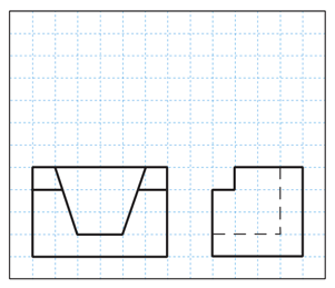
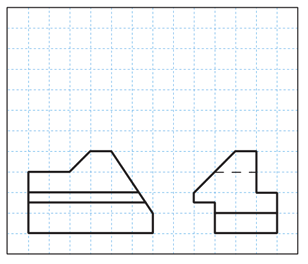
Component A
Given Orthographic Views
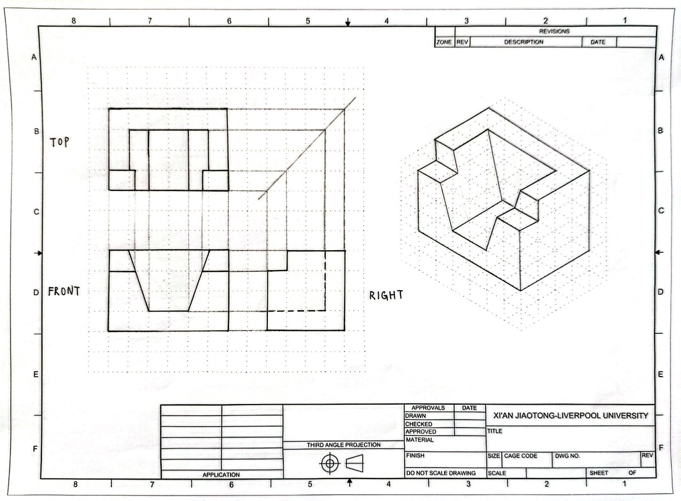
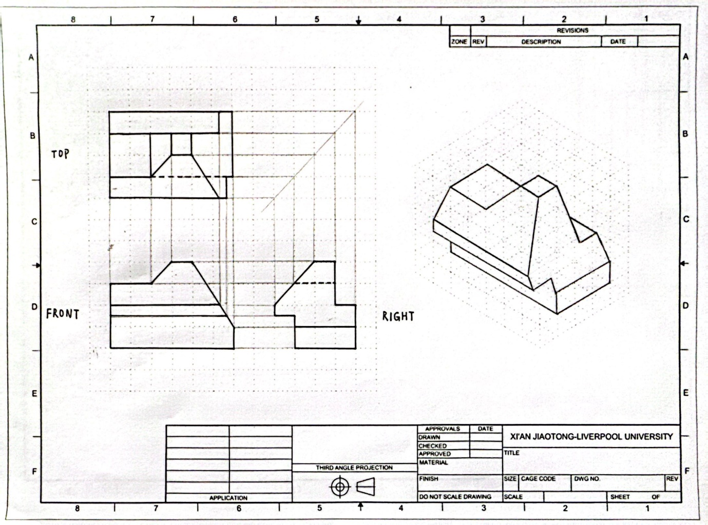
Final Drawing
The front view and right-side view were first interpreted to reconstruct the geometry of the object. Based on this, the missing top view and the isometric sketch were produced.
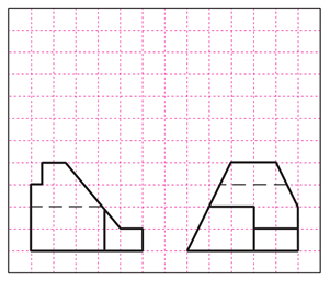
Component B
Given Orthographic Views
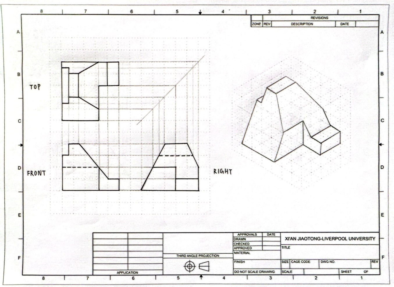
Final Drawing
For Component B, the missing top view was first derived using auxiliary construction lines, which clarified the geometry before producing the isometric sketch.
Component C
Given Orthographic Views
Final Drawing
The geometry of Component C was reconstructed from the given projections, and the complete multiview drawings and isometric sketch were produced.
Section Summary
This section demonstrates the process of reconstructing three-dimensional geometry from orthographic projections. For each component, the given views were interpreted, missing views were derived, and isometric sketches were produced to represent the final 3D form.
Section B – 3D Modeling of Given Objects
Assignment Requirement
Two engineering components with full dimensions were provided.
The task required:
- constructing 3D models using Creo
- generating multiview engineering drawings suitable for manufacturing
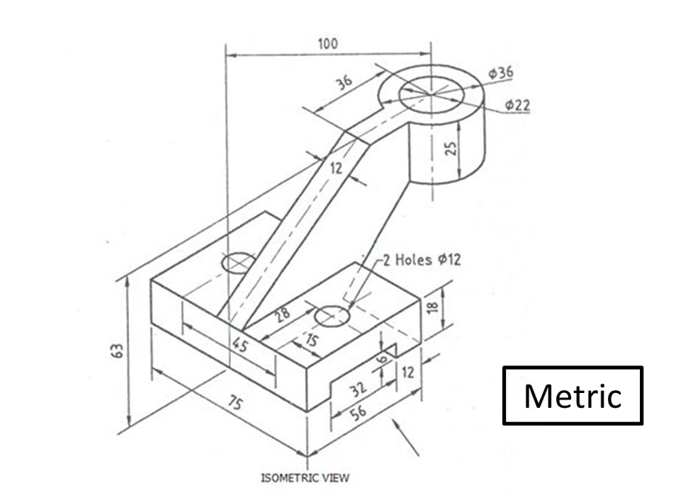
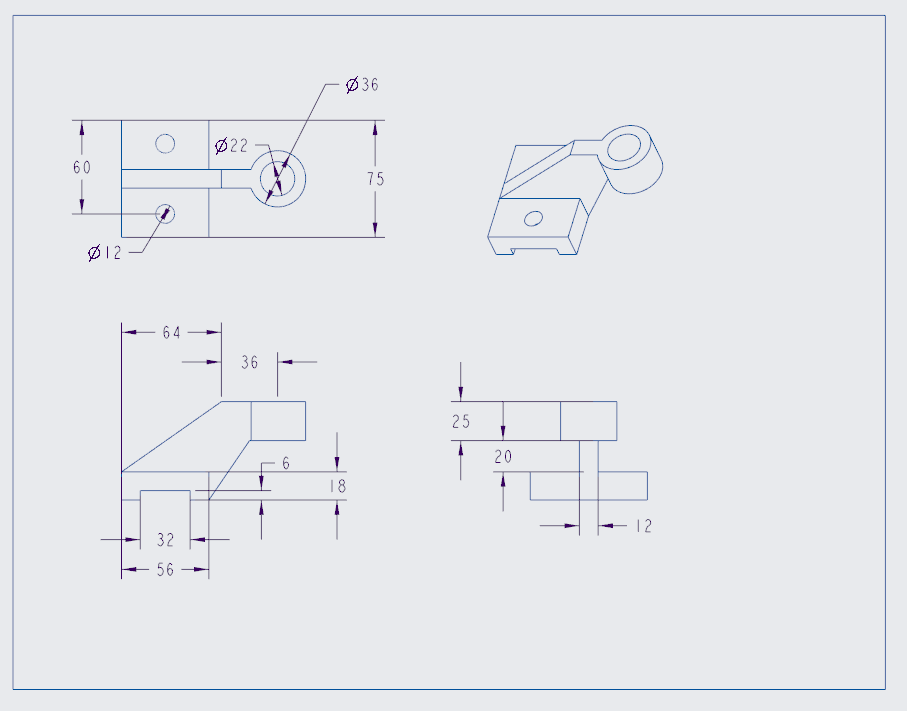
Object 1
Given Engineering Drawing
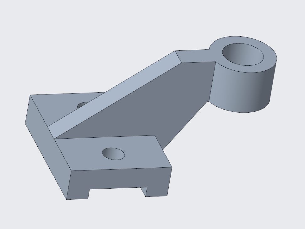
3D CAD Model
The geometry was reconstructed in Creo using parametric modelling features such as Extrude, Hole, Plane, and Mirror.
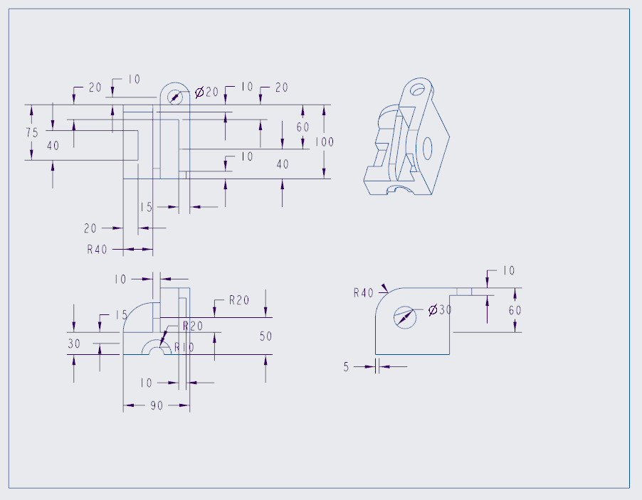
Engineering Drawing
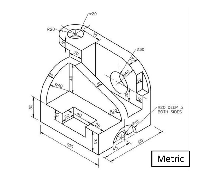
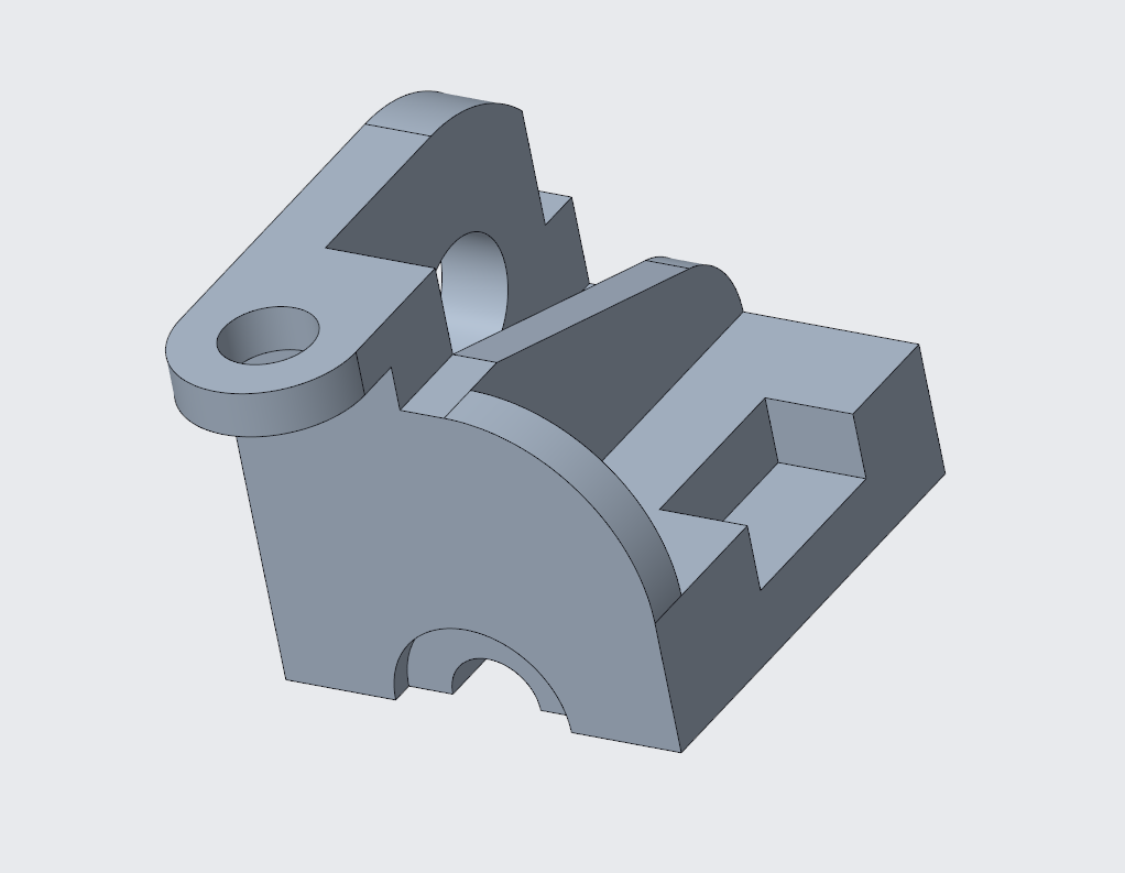
Object 2
Given Engineering Drawing
3D CAD Model
Engineering Drawing
Section Summary
This section demonstrates the workflow from interpreting dimensioned engineering drawings to constructing parametric 3D models and generating manufacturing-ready multiview drawings using CAD.
Section C – Guitar Holder Design
Design Requirement
The final section of the coursework involved an open-ended design task.
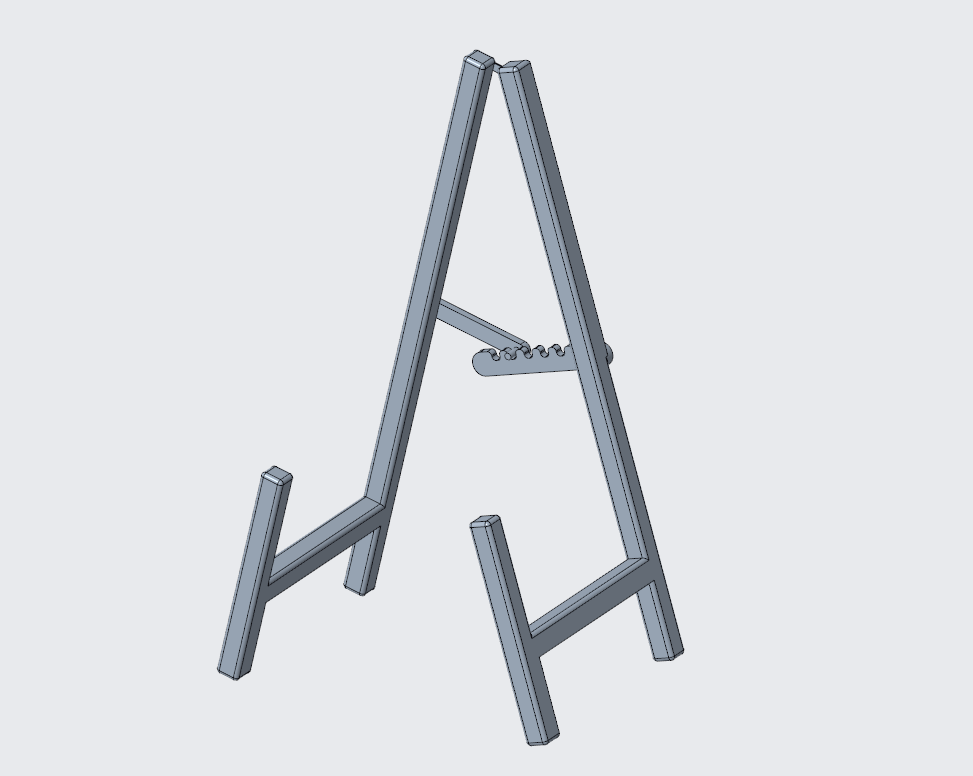
The objective was to design a guitar holder using Creo and produce a corresponding engineering drawing suitable for manufacturing.
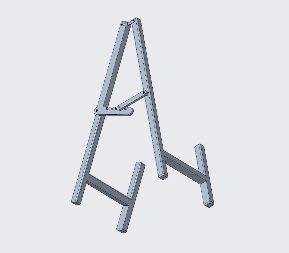
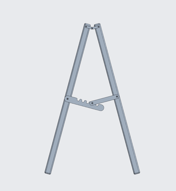
Design and CAD Model
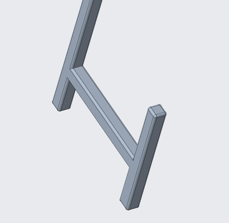
The design process began by considering the functional requirements of the holder, including stability, safe contact with the instrument, and adaptability.
A complete 3D CAD model of the guitar holder was then developed in Creo, representing the overall structure and supporting mechanism.
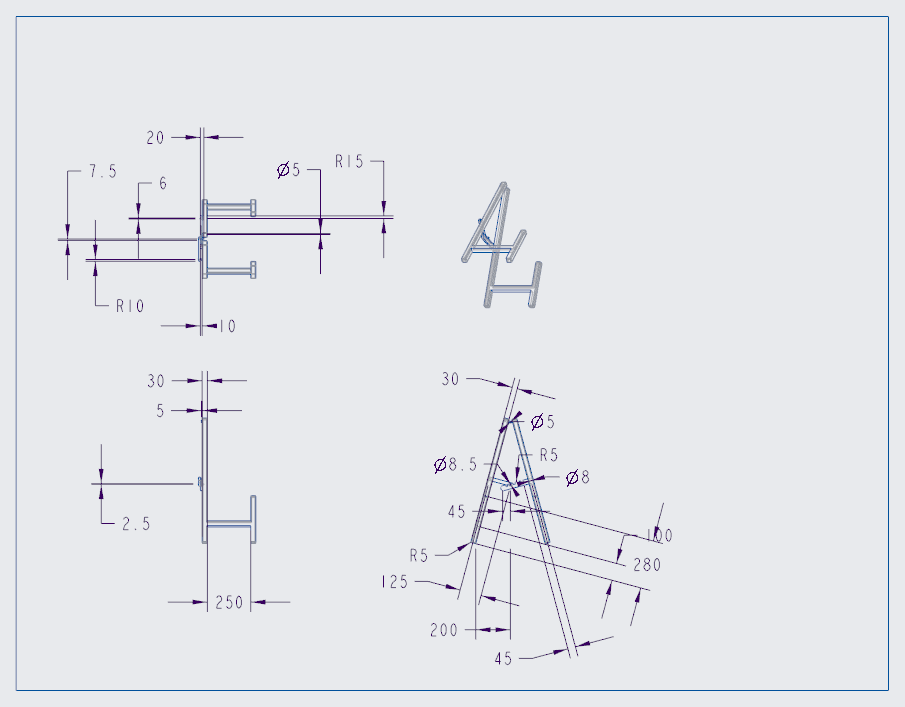
Engineering Drawing
After completing the CAD model, multiview engineering drawings were generated in Creo to provide the necessary information for manufacturing.
Key Design Features
Triangular Support Structure
A triangular structure was used to improve stability and reduce the likelihood of tipping.
Rounded Contact Edges
Edges that may come into contact with the guitar were rounded with a radius of 5 mm to prevent damage.
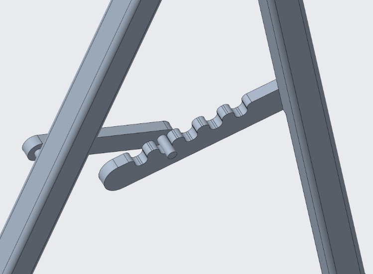
Adjustable Mechanism
An adjustable mechanism was introduced to allow the angle between the support legs to be modified, making the holder adaptable to different guitar sizes.
Section Summary
This section demonstrates the transition from design requirements to a complete CAD model and engineering drawing. The final design integrates stability, protection, and adjustability into a manufacturable structure.
Conclusion
This coursework demonstrates the complete workflow of engineering drawing, from interpreting orthographic projections to constructing 3D CAD models and developing an original design.
Section A focused on reconstructing three-dimensional geometry from given projection views through manual drawing. Section B extended this process into CAD modelling, where engineering components were built in Creo and translated into manufacturing-ready drawings. Section C introduced an open-ended design task, applying these skills to develop a functional guitar holder with structural stability, protective features, and basic adjustability.
Overall, the project integrates engineering drawing, spatial visualisation, CAD modelling, and design thinking into a coherent process, reflecting the transition from representation to realisable engineering design.